 Parameter
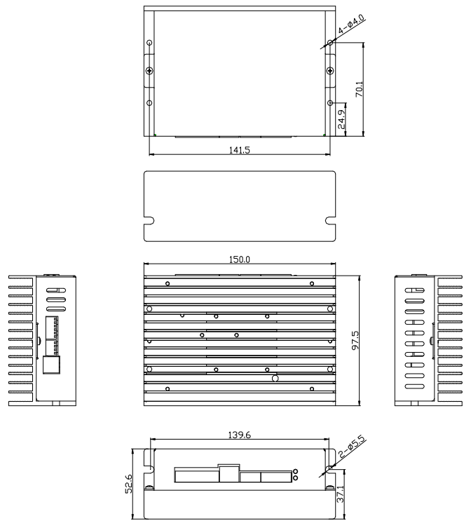
 Overall Dimensions
 Download
 Cooperation
Features :
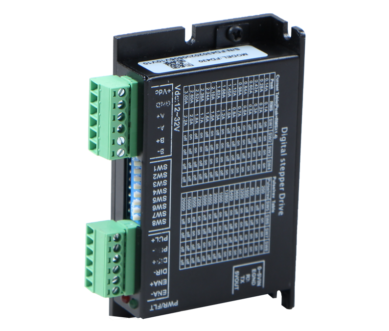
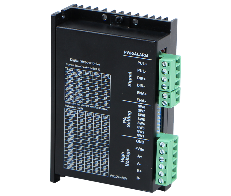
● CL2505 adopts the latest 32 bit special motor control DSP chip and optimized closed-loop control technology
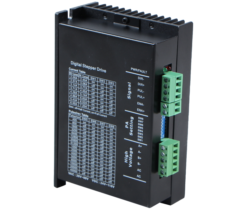
● Input voltage from 20VAC~80VACor 30VDC-110VDC
● Continuous output effective current:6.0A (Max), uitable for 60mm, 86mm series closed-loop stepper motor
● Input signal level is compatible 5V~24V, Maximum pulse response frequency up to 500KHz (Factory default is 200KHz)
● Pulse, Direction, Enable differential signal input, giving consideration to differential, common-anode and common-cathode connection method.
● Common-cathode connection method of output signal,alarm, pend signal, Z signal, brake control. The position and Z signal dial switch can be set.
● Micro-step dial switch setting(200-51200), When all the Micro-step dial switch is ON, the upper computer can modify any Micro-step at will.
● Pulse direction and CW&CCW control mode, open and closed loop mode selection, smoothing filter time can be set by dialing code.
● With protection functions from over - voltage, under - voltage, over - current and position following error.
● Performance: smooth motion, super-low motor noise, small overshoot, small position following error.
Typical application:
Suitable for medium and small automation machines and equipment, such as electronics manufacturing equipment, 3C non-standard automation equipment, screw machine, peeler machine, winding machine, crimping machine, laser cutters, marking machine, inkjet printers, engraving machines, automatically crawl devices, Special CNC numerical control machine tool, packing devices, robots and so on.
Product overview :
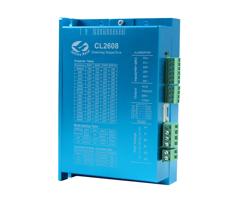
CL2608 adopts the latest special motor control DSP chip and optimized closed-loop control technology which can reduce the motor vibration, effectively reduce the motor heating, prolong the motor lifespan through the intelligent regulation of current. The high speed torque attenuation is much lower than that of the ordinary open-loop driver, which can greatly improve the high speed performance and torque utilization rate of the stepper motor, thus improving the efficiency and precision of the machine.
It is very convenient for clients to monitor and control by the Built-in output signals - PEND, ALARM, BRAKE and to ensure the safe operation of processing equipment by alarm function of position following error. Two groups of 10-bit dial switch can be used for a number of common function settings, including pulse direction and CW&CCW control mode, open and closed loop mode selection, instruction smoothing filter time and so on, which can make debugging more convenient. Fulling is committed to providing customers with cost-effective motor control solutions.
DIP Switch Configuration :
Microstep | 2 | 4 | 8 | 16 | 32 | 64 | 128 | 256 | 5 | 10 | 20 | 25 | 40 | 50 | 100 | 200 |
PU/Rev | 400 | 800 | 1600 | 3200 | 6400 | 12800 | 25600 | 51200 | 1000 | 2000 | 4000 | 5000 | 8000 | 10000 | 20000 | 40000 |
SW10 | ON | ON | ON | ON | ON | ON | ON | ON | OFF | OFF | OFF | OFF | OFF | OFF | OFF | OFF |
SW9 | ON | ON | ON | ON | OFF | OFF | OFF | OFF | ON | ON | ON | ON | OFF | OFF | OFF | OFF |
SW8 | ON | ON | OFF | OFF | ON | ON | OFF | OFF | ON | ON | OFF | OFF | ON | ON | OFF | OFF |
SW7 | ON | OFF | ON | OFF | ON | OFF | ON | OFF | ON | OFF | ON | OFF | ON | OFF | ON | OFF |
SW6 | Pluse smoothing filter time: | OFF | Default | ON | 3ms | OFF | 12ms | ON | 40ms | |||||||
SW5 | OFF | OFF | ON | ON | ||||||||||||
SW4 | PEND/Z Function selection: OFF:PEND position output ON:Z signal output. | |||||||||||||||
SW3 | Control mode choice: OFF: closed-loop mode; ON: open-loop mode. | |||||||||||||||
SW2 | Motor direction: OFF:CCW ON:CW | |||||||||||||||
SW1 | Pulse direction and CW&CCW control mode: OFF:PU&DR ON:CW&CCW | |||||||||||||||
Interface description :
| Signal | Function | Description |
| PWR | Power indicator | The green indicator light is on when the power is on. |
| ALARM | Fault indicator | The blinking period is 5 seconds. The number of blinking indicates fault information. One time indicates over-current, two times indicates over-voltage, three times indicates under-voltage, five times indicates position following fault . |
| PU+ | Pulse positive input | At pulse positive input, +5V to +24V can drive. If the input signal is higher than +24V, the current limiting resistor must be connected to the PU- port. |
| PU- | Pulse negative input | The falling edge is effective, and the motor takes one step whenever the pulse changes from high to low. |
| DR+ | Direction positive input | At direction positive input, +5V to +24V can drive. If the input signal is higher than +24V, the current limiting resistor must be connected to the PU- port. |
| DR- | Direction negative input | Used to change the motor direction. |
| MF+ | Enable positive input | At enable positive input, +5V to +24V can drive. If the input signal is higher than +24V, the current limiting resistor must be connected to the PU- port. |
| MF- | Enable negative input | When effective, the motor releases, and has the function of clearing the position error alarm. |
| ALM | Alarm signal output | When there is over-current, over-voltage, under-voltage, position error alarm, the alarm signal is effective (the output optocoupler is on).ALM is connected to the pull resistance to the positive pole of the output power supply. COM- is connected to the negative pole of the output power supply. The maximum driving current is 50mA. |
| PEND/Z | PEND/Z signal output | When SW4 is OFF, the PEND/Z signal outputs, and when the driver finishes the given pulse, the PEND/Z signal is effective (the output optocoupler is on). When SW4 is ON, the motor turns once and there is one Z signal output. The interface is connected with a pull resistor to the positive pole of the output power supply, and COM- is connected to the negative pole of the output power supply. The maximum driving current is 50mA. |
| BRK | Brake signal output | When the driver is powered on, the brake signal is controlled by timing logic. The brake signal controls the timing of the brake motor operation. See the instruction of connection method for more details. The maximum driving current is 100mA. |
| COM- | Common signal output | Common signal output. |
| +5V/GND | Encoder 5V/GND | Connect to 5V power supply and ground of encoder signal |
| EZ+/EZ- | Encoder channel Z differential input | Connect to EZ+/EZ- of encoder |
| EB+/EB- | Encoder channel B differential input | Connect to EB+/EB- of encoder |
| EA+/EA- | Encoder channel A differential input | Connect to EA+/EA- of encoder |
| A+/A- | Motor line A-phase | Lead wire A+/A- of motor A-phase |
| B+/B- | Motor line B-phase | Lead wire B+/B- of motor B-phase |
| V+/V- | Power supply input | Driver power supply: 20VAC~80VAC or 30VDC-110VDC |
Note:
1. Please ensure that the wiring of the motor and encoder is correct, otherwise the position error alarm will appear after the driver is powered on and receives pulse signals.
2. In motor assembly, it is strictly forbidden to knock on the rear end cover of the motor to avoid damaging the encoder.
| User's Manual For CL2608 Pulse Type Closed-loop Stepper Driver | 522.97 KB |

|

Hotline
+86-519-85132957

Address
69 Kunlun Road, Xinbei District, Changzhou City, Jiangsu ProvinceCopyright 2023 Copyright Changzhou Fulling Motor Co., Ltd
【 Disclaimers 】