 Parameter
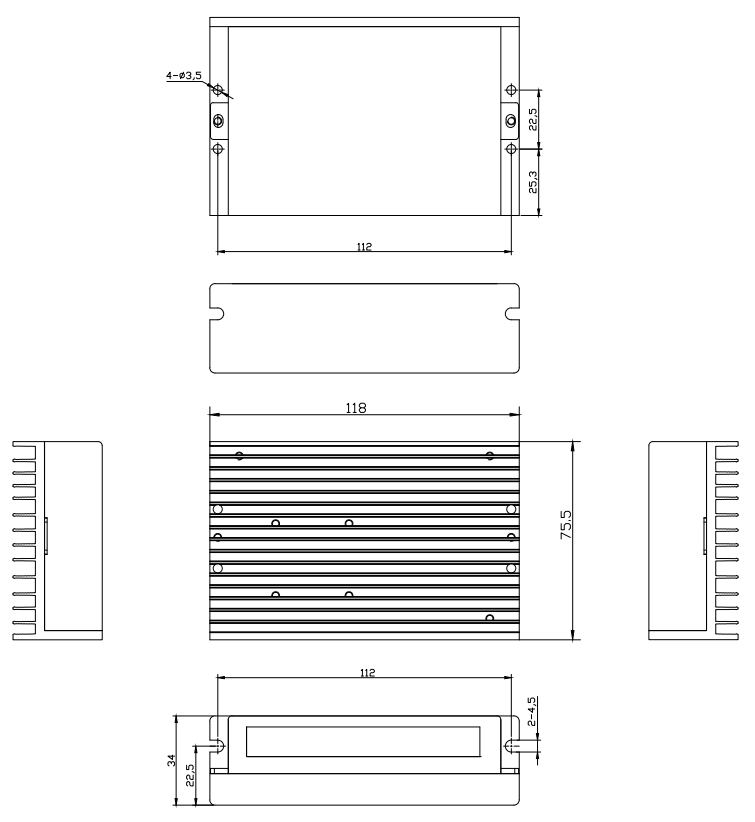
 Overall Dimensions
 Download
 Cooperation
Features :
● New 32-bit DSP Technology
● Ultra-low vibration noise
● Built-in high micro-step, ranging from 200 to 51200
● Motor auto-identification and parameter auto-configuration technology.
● Variable current control for less motor heating
● Automatic idle-current reduction in half
● Suitable for 4,6,8 lead 2-phase motors
● Optically isolated differential signal input
● Pulse frequency up to 500 KHz(default 200KHz)
● Output current programmable, from 0.1A to 5.6A
● Driver power supply: DC:+24V-50V
● Over-voltage, Under-voltage, over-current protections
Typical application:
FD430 can be used in various kinds of small and medium-sized equipment and machines, such as engraving machines, labeling machines, laser cutters, laser typesetting, plotting instrument, CNC machine, automatic assembly equipment, and so on. Particularly adapt to the applications desired with low noise, high speed.
Product overview :
The FD556 is the company’s new digital stepping driver based on the latest 32-bit DSP digital processing technology. Drive control algorithm uses advanced variable current technology and advanced frequency conversion technology. The driven motors can run with low heating, small noise, smooth movement. Users can set any micro-step within 200~51200 and any current value within the rated current, which can meet the needs of most applications. Thanks to the built-in micro-resolution technology, the effect of high resolution can be achieved and the driven motors can run with much smaller noise, lower heating, smoother movement at low to high speed even under low resolution conditions. Motor auto-identification and parameter auto-configuration technology offers optimum responses with different motors and easy-to-use.
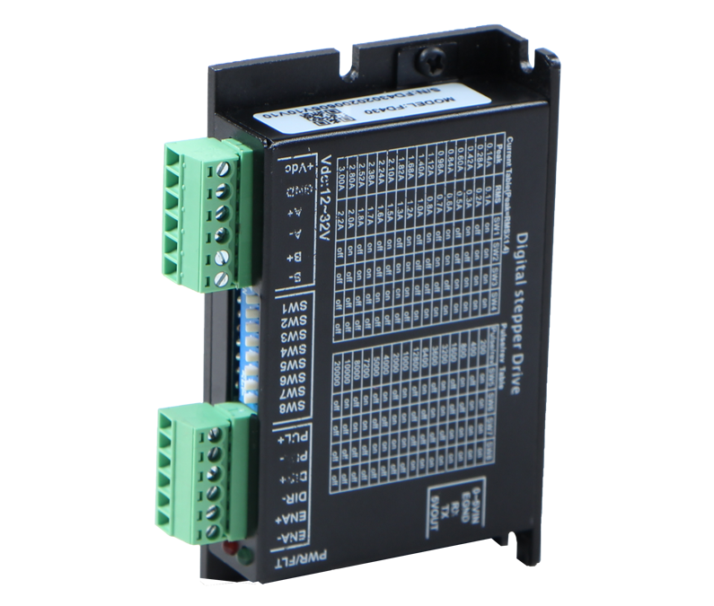
Microstep Resolution Selection :
Microstep | 18 | 2 | 4 | 8 | 16 | 32 | 64 | 128 | 5 | 10 | 20 | 25 | 40 | 50 | 100 | 125 |
PU/Rev | 3600 | 400 | 800 | 1600 | 3200 | 6400 | 12800 | 25600 | 1000 | 2000 | 4000 | 5000 | 8000 | 10000 | 20000 | 25000 |
SW8 | ON | ON | ON | ON | ON | ON | ON | ON | OFF | OFF | OFF | OFF | OFF | OFF | OFF | OFF |
SW7 | ON | ON | ON | ON | OFF | OFF | OFF | OFF | ON | ON | ON | ON | OFF | OFF | OFF | OFF |
SW6 | ON | ON | OFF | OFF | ON | ON | OFF | OFF | ON | ON | OFF | OFF | ON | ON | OFF | OFF |
SW5 | ON | OFF | ON | OFF | ON | OFF | ON | OFF | ON | OFF | ON | OFF | ON | OFF | ON | OFF |
Note: When SW5, SW6, SW7 and SW8 are all on, the upper computer can be modified into any microstep within 200-51200.
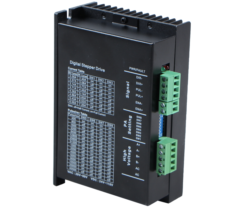
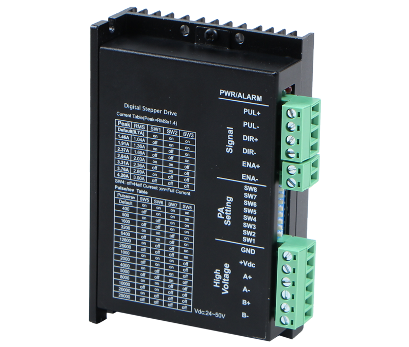
Dynamic current Setting :
Current peak | Default | 2.1A | 2.7A | 3.2A | 3.8A | 4.3A | 4.9A | 5.6A |
Current RMS | Default | 1.5A | 1.9A | 2.3A | 2.7A | 3.1A | 3.5A | 4.0A |
SW3 | OFF | OFF | OFF | OFF | ON | ON | ON | ON |
SW2 | OFF | OFF | ON | ON | OFF | OFF | ON | ON |
SW1 | OFF | ON | OFF | ON | OFF | ON | OFF | ON |
SW4 | SW4 is used for standstill current setting. off means that the standstill current is set to be half of the selected dynamic current, and on means that standstill current is set to be the same as the selected dynamic current. In general SW4 should be set to off to enable the heat generation of the motor and driver to be reduced and the reliability to be improved. The current automatically reduced to 60% of dynamic current setting 400 millisecond after the last pulse. Theoretically, This will reduce motor heating to 30% (due to P=I2*R)) of the original value. | |||||||
When SW1,SW2.SW3 are set to off, it can be set to the required current by PC Software, Maximum value is 5.6A and resolution is 0.1A, If it is not set, the default is 1.4A.
Interface description :
Signal | Function | Description |
PWR | Power indicator | The green indicator light is on when the power is on. |
ALARM | Fault indicator | The blinking period is 3 seconds. The number of blinking indicates fault information. One time indicates over-current, and two times indicates over-voltage. |
PU+ | Pulse positive input | At pulse positive input, +5V to +24V can drive. If the input signal is higher than +24V, the current limiting resistor must be connected to the PU- port. |
PU- | Pulse negative input | The falling edge is effective, and the motor takes one step whenever the pulse changes from high to low. |
DR+ | Direction positive input | At direction positive input, +5V to +24V can drive. If the input signal is higher than +24V, the current limiting resistor must be connected to the PU- port. |
DR- | Direction negative input | Used to change the motor direction. |
ENA+ | Enable positive input | At enable positive input, +5V to +24V can drive. If the input signal is higher than +24V, the current limiting resistor must be connected to the PU- port. |
ENA- | Enable negative input | When effective, the motor releases, and has the function of clearing the position error alarm. |
A+/A- | Motor line A-phase | Lead wire A+/A- of motor A-phase |
B+/B- | Motor line B-phase | Lead wire B+/B- of motor B-phase |
V+/V- | Power supply input | Driver power supply: DC:+24V-50V |
| User's Manual for FD542 Digital 2-Phase Stepper Driver | 563.7 KB |

|
| User's Manual for FD556 Digital 2-Phase Stepper Driver | 585.02 KB |
|

Hotline
+86-519-85132957

Address
69 Kunlun Road, Xinbei District, Changzhou City, Jiangsu ProvinceCopyright 2023 Copyright Changzhou Fulling Motor Co., Ltd
【 Disclaimers 】